Tel : +86-13812850975 E-mail : info@winsoarst.com

Views: 0 Author: Site Editor Publish Time: 2026-08-29 Origin: Winsoar


Direct answer: Choose a vacuum calibration table for PVC profile production according to the profile drawing, calibration mould, profile width and height, cooling demand, target line speed, haul-off arrangement and dimensional tolerance. The table must work as one system with the profile die and calibration mould; selecting it by table width alone can lead to unstable sizing, surface marks and profile deformation.
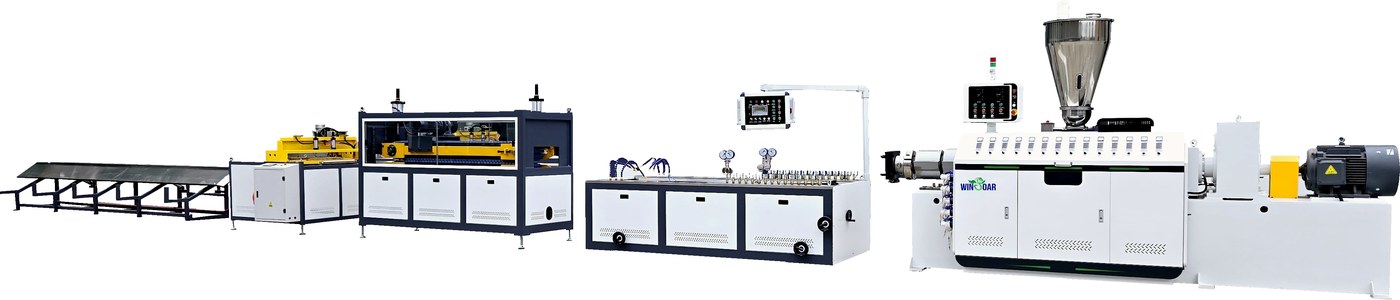
The vacuum calibration table is one part of a complete PVC profile extrusion line.
A vacuum calibration table is the sizing and cooling section installed after the PVC profile die. The hot extruded profile enters a matched calibration mould inside the table. Controlled vacuum draws the profile wall against the mould surface while circulating water removes heat and stabilizes the profile section.
This section is especially important for window profiles, door profiles, decorative profiles, skirting, cable trunking and other rigid PVC profiles with visible surfaces, hollow chambers or tight dimensional requirements. The table does not create the profile geometry by itself. The die and calibration mould define the section, while the table provides support, vacuum, cooling and adjustment during the transition from melt to stable product.
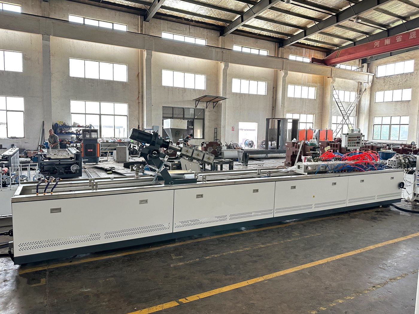
Vacuum calibration and cooling stabilize the dimensions and surface of the extruded PVC profile.
After leaving the die, PVC remains hot enough to deform under its own weight, haul-off tension and cooling shrinkage. The calibration table controls this unstable section until the profile has enough strength to travel through the haul-off. If vacuum, water flow or alignment is unsuitable, the profile may leave the table with a dimension that cannot be corrected downstream.
Profile width and height can change during cooling.
Hollow chambers can collapse when support or vacuum is insufficient.
Uneven cooling can cause twist, bowing or local shrinkage.
Incorrect mould adjustment can create scratches or visible drag marks.
Insufficient effective length can limit output even when the extruder has spare capacity.
Unstable haul-off speed can transfer dimensional variation into the finished profile.
For this reason, the calibration table should be evaluated together with the die, mould, extruder output and downstream haul-off rather than as a low-cost accessory.
The PVC melt exits the profile die with the required approximate section.
The hot profile enters the calibration mould and is supported by the table.
Vacuum ports hold the profile against the mould surfaces and help define the outside dimensions.
Cooling water removes heat through the mould and table circulation system.
Operators adjust table position, mould alignment, vacuum and water flow during commissioning.
The haul-off pulls the cooled profile at a controlled speed toward cutting, stacking or other downstream equipment.
The operating window is a balance. More vacuum is not automatically better: excessive or uneven vacuum can leave marks, disturb thin walls or make a profile difficult to release. Water flow and temperature must also be stable across the effective calibration length.
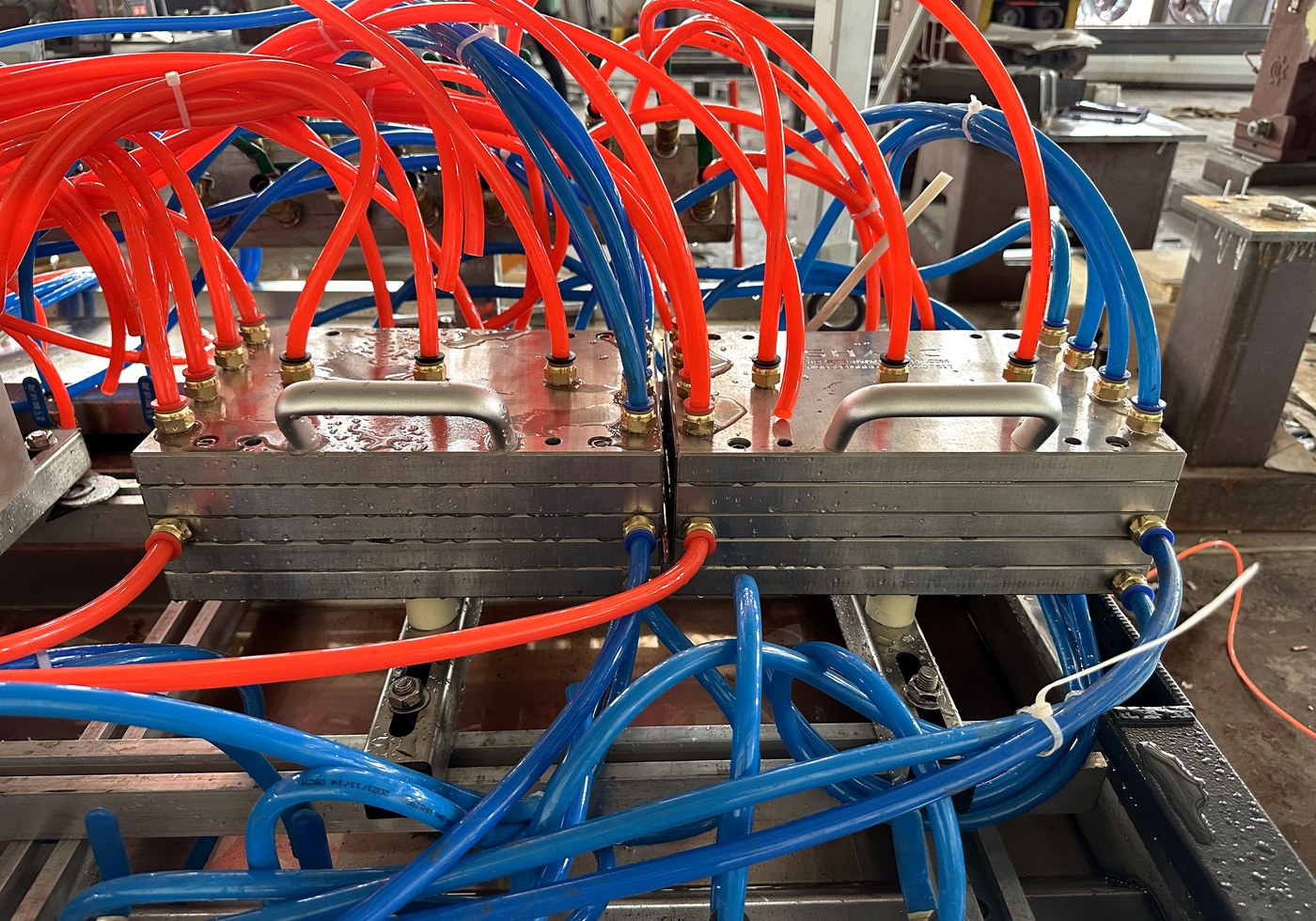
The calibration mould must match the profile drawing and fit the table's vacuum and cooling arrangement.
The profile die distributes the PVC melt into an approximate shape. The calibration mould then establishes the final external dimensions while the material is still hot. The table houses and supports this mould, provides vacuum and cooling connections, and allows the operator to align the profile path with the haul-off.
Section | Main responsibility | Information needed before selection |
|---|---|---|
Profile die | Distributes and forms the hot PVC melt. | Profile drawing, material, wall structure, output and surface requirement. |
Calibration mould | Sets the profile section and supports dimensional stability. | Exact profile geometry, tolerances, hollow chambers and cooling contact. |
Vacuum calibration table | Provides mould support, vacuum, water cooling and adjustment. | Mould size, line speed, cooling demand, table width, length and layout. |
Haul-off | Pulls the stabilized profile at a controlled speed. | Profile surface, traction, width, output and cutting or stacking method. |
A quotation that lists an extruder and table without identifying the profile drawing or calibration mould is incomplete. The tooling and table should be checked as a matched set.
Measure the finished profile section, not only the nominal product name. A wide window profile, a narrow decorative strip and a multi-chamber frame profile place different demands on mould support and cooling. Hollow sections also require correct internal support so that the walls do not collapse or distort.
The table must accept the required calibration mould and leave enough adjustment space for alignment. Confirm mould length, connection positions, vacuum ports, water connections and changeover method. If several profiles are planned, list every mould set instead of assuming that one universal mould will fit all sections.
Useful length is more important than the outside frame dimension. The supplier should state how much length is available for actual sizing and cooling. Required length depends on profile mass, wall thickness, formula, output, line speed, water circulation and ambient conditions.
Ask how vacuum is divided across the mould, how it is adjusted and how the system is drained and cleaned. A stable vacuum circuit helps keep the profile against the mould without creating uneven suction. The quotation should identify the pump, control method, ports and service access.
Cooling should remove heat evenly across the profile. Check the water tank, pump, spray or circulation arrangement, drainage, filtration and temperature monitoring. For profiles with different wall thicknesses or visible surfaces, uneven water flow can become a quality problem before the operator notices a temperature change.
The table should allow practical adjustment in the vertical, horizontal and longitudinal directions. Alignment is needed when changing moulds, correcting profile twist or matching the haul-off centerline. Adjustment mechanisms should be accessible during commissioning and routine maintenance.
The profile path from die to table to haul-off should remain straight and stable. Confirm the usable table width, haul-off contact method, profile surface protection, line speed control and the transition to cutter, stacker or coiler. A table that performs well in isolation can still cause problems if the downstream centerline or traction is mismatched.
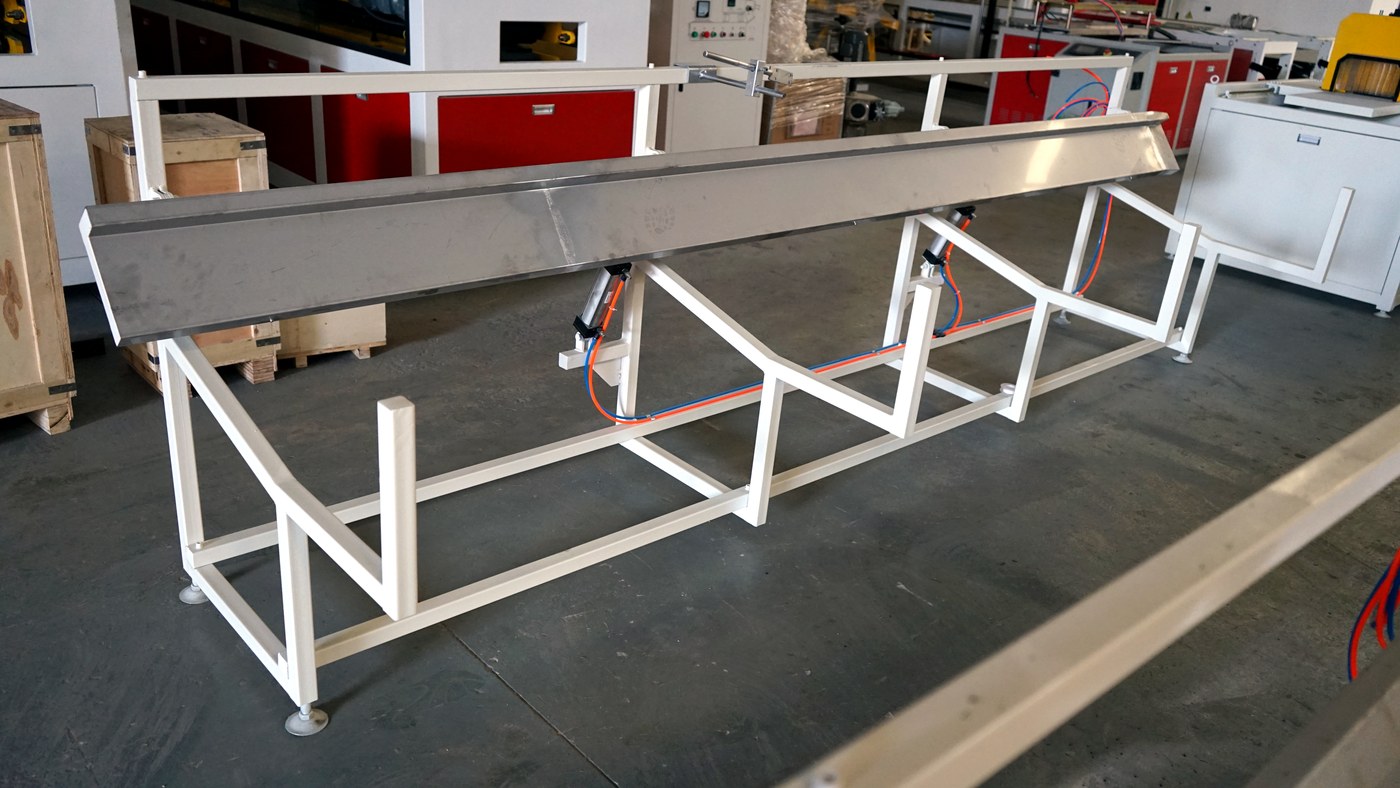
The calibration section must be coordinated with haul-off and finished-profile handling.
Prepare the latest profile drawing with dimensions, tolerances and hollow sections.
Confirm the PVC material formula, filler or recycled content and required surface finish.
Set target output, line speed, profile length and production schedule.
Define the calibration mould structure and the number of mould sets required.
Match table width, effective length, vacuum zones and cooling capacity to the mould.
Check the haul-off, cutter, stacker and workshop centerline.
Confirm water supply, drainage, electrical voltage, compressed air and maintenance access.
Request a layout drawing and commissioning scope before approving the quotation.
For a complete equipment review, see the PVC Profile Extrusion Line. The broader Profile Production Line category and PVC and WPC Profile Production Line category can help compare related configurations.
Observed problem | First checks |
|---|---|
Profile width is unstable | Check melt temperature and pressure, vacuum stability, mould alignment, water flow and haul-off speed. |
Profile twists after the table | Check uneven cooling, mould centerline, table leveling, die alignment and haul-off traction. |
Surface has drag marks | Check mould finish, vacuum level, debris, water cleanliness and profile contact pressure. |
Hollow chamber collapses | Check calibration mould support, internal geometry, melt strength, cooling rate and haul-off tension. |
Output cannot reach the target | Check whether effective cooling length, vacuum capacity and haul-off speed match the extruder output. |
Commissioning should use the intended PVC formula and the approved profile tooling. A test using a different material or temporary mould may produce misleading conclusions about table capacity.
Send the following information when requesting a PVC profile vacuum calibration table or a complete extrusion line quotation:
Profile drawing in a readable CAD or PDF format.
Profile width, height, wall thickness and dimensional tolerance.
Number and shape of hollow chambers.
PVC resin, additives, filler and recycled-material information.
Target output, line speed and expected working hours.
Surface finish, color, co-extrusion or lamination requirements.
Required calibration mould quantity and changeover frequency.
Cutting length, stacking method and packaging arrangement.
Factory voltage, water conditions, drainage and workshop dimensions.
Destination country and applicable product or safety standards.
The PVC Profile Extrusion Line running video on YouTube shows the complete equipment context around extrusion, calibration and downstream handling. Reviewing the complete line is useful because the calibration table must be coordinated with the extruder, mould, haul-off and stacker.
For related equipment, review the Plastic Profile and Board Production Line category, the Plastic Extruder category and the PVC Profile Extrusion Line machine configuration article.
It supports the hot PVC profile after the die and uses matched mould support, controlled vacuum and water cooling to stabilize the final profile dimensions, hollow sections and surface shape.
No. Profile height, wall thickness, hollow-chamber structure, calibration mould, target output, line speed, cooling demand and haul-off arrangement also affect the correct table specification.
The required effective length depends on the profile section, material temperature, wall thickness, output, line speed and cooling efficiency. The supplier should confirm useful calibration and cooling length against the actual drawing rather than quoting only the frame length.
Provide the profile drawing, dimensions and tolerances, PVC formula, target output, line speed, surface requirement, calibration mould quantity, cutting method, local voltage, water conditions and workshop layout.
One line may run several profiles when its width, adjustment range, vacuum and cooling capacity, haul-off and downstream equipment are suitable. Each profile normally needs a matched calibration mould, and the practical changeover time should be confirmed.